

How Machine Vision Helps Detect Fabric Defects Before Cutting
A fabric roll can look acceptable at goods-in and still create trouble in the cutting room. A hole may fall inside a front panel, a needle line may cross multiple lays, or a stain may force recutting. Machine vision aims to locate these irregularities while the material is still a roll and the factory still has options.
The camera is only the beginning. Useful detection requires controlled imaging, fabric-appropriate analysis, position tracking, and a workflow that converts a finding into a cutting decision. Without those connections, bounding boxes on a screen add little to production.
Quick Answer
Machine vision helps detect fabric defects before cutting by capturing images of moving fabric under controlled lighting, analyzing those images for abnormal color, texture, structure, or geometry, and linking each suspected defect to a position on the roll. The output may identify a hole, stain, broken yarn, dropped stitch, crease, print fault, or other configured irregularity and record its location across the fabric width and along the roll length.
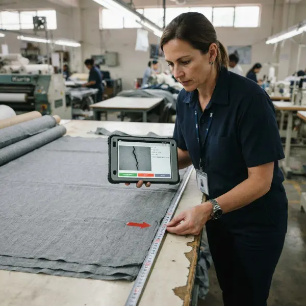
That location data can be converted into a defect map for incoming inspection, spreading, marker planning, splicing, panel avoidance, roll allocation, or manual verification. The practical benefit is not merely faster visual inspection. It is the opportunity to prevent a known defect from being cut into a garment component.
Performance is conditional. Camera resolution, lighting angle, fabric tension, line speed, surface texture, pattern complexity, training data, and defect definition all influence what the system can see. Machine vision also does not measure every quality property. Human review and physical testing remain necessary for subjective appearance, tactile issues, color assessment outside the calibrated setup, and non-visual performance requirements.
What Is Machine Vision in Fabric Inspection?
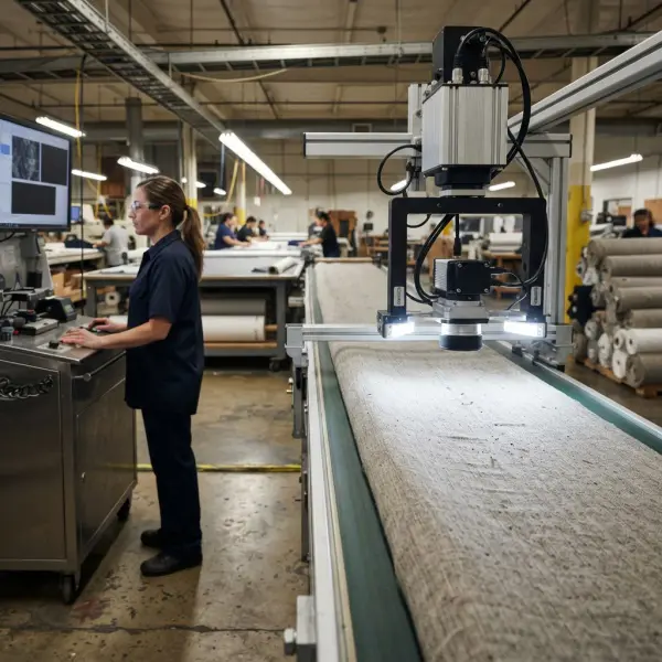
Machine vision is a technical system that uses cameras or optical sensors, controlled illumination, image processing, and decision software to examine fabric and produce actionable information about visible irregularities. In this context, its job is usually to determine whether a suspicious feature exists, where it is located, how large it appears, and sometimes which defect category it resembles.
Machine vision is not identical to the complete inspection operation. The broader automated fabric inspection process also includes fabric transport, tension control, roll identification, grading rules, reporting, operator review, maintenance, and downstream action. Machine vision is the optical and analytical layer within that system.
It is also useful to separate four tasks that are often grouped together:
|
Machine-vision task |
Question it answers |
Typical output |
|
Classification |
What does this image or region contain? |
Defect class, normal class, or probability |
|
Detection |
Is there a defect, and where is it? |
Class label plus bounding box |
|
Segmentation |
Which pixels belong to the affected area? |
Detailed defect mask or outline |
|
Anomaly detection |
Does this region depart from learned normal fabric? |
Anomaly score and possible location |
These outputs serve different needs. A bounding box may guide inspection; pixel-level segmentation can estimate an irregular area more precisely. Anomaly detection helps when defect samples are scarce but may flag harmless variation if “normal” data do not represent production.
Why Detect Defects Before Fabric Is Cut?
Before cutting, the factory can still decide how to use the roll. It may avoid an affected area, insert a splice, change roll allocation, reserve cleaner material for prominent garment panels, request replacement fabric, or hold the roll for supplier review. After cutting, many of those choices become recutting, re-bundling, line disruption, or accepting a quality risk.
Not every fault can be avoided economically. Wide markers, directional prints, nap, stripe matching, shade continuity, and size ratios constrain placement, while extensive damage may require downgrading the roll. Detection nevertheless gives the team a decision window before spreading or cutting.
This connection is particularly important in fabric cutting process control. Cutting converts flexible material into order-specific components. Once panels are mixed into bundles, tracing a fabric fault back to its exact roll position becomes harder, and replacing one piece may affect shade consistency or bundle sequence.
How Does Machine Vision Turn Fabric Images into Defect Locations?
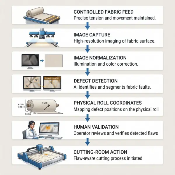
The workflow begins before any algorithm runs. The fabric has to move predictably, the optics need a stable view, and the system needs an accurate relationship between image coordinates and physical roll coordinates. Only then can a software finding become useful to production.
1. The system presents the fabric to the camera
Fabric passes through an inspection zone under controlled speed and tension. Rollers or web-guiding components keep the surface within the camera’s field of view. Wrinkles, vibration, wandering edges, dust, and uneven tension can change the appearance of normal fabric or conceal actual faults.
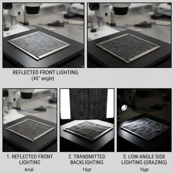
The image-acquisition design depends on the material. Reflected light reveals surface color and texture; transmitted light can make holes, missing yarns, and density changes easier to see. Angled illumination may emphasize raised fibers or surface relief. Multiple light directions or sensors may be needed when one arrangement cannot reveal all critical defects.

2. Cameras convert the moving surface into digital images
Line-scan cameras are well suited to continuous webs because they capture one narrow line at a time while the fabric moves. The software assembles those lines into a two-dimensional image. Area-scan cameras capture rectangular frames and may be suitable for slower movement, defined fields of view, prototypes, or particular inspection geometries.
Neither camera type is automatically superior. Selection depends on fabric width, minimum defect size, speed, color fidelity, lens coverage, working distance, computing capacity, and synchronization. Resolution should be expressed at the fabric surface, such as pixels per millimetre, not only as megapixels.
A 2026 research dataset called RAW-FABRID was acquired with controlled LED illumination and a line-scan camera, producing high-resolution grayscale images with detailed annotations. Its documented acquisition setup and dataset scope are useful precisely because they state the boundary: the dataset focuses on structural and textural defects in raw plain-weave cotton and is not intended for color anomalies. A camera arrangement and dataset designed for one problem should not be presented as universal.
3. Pre-processing reduces avoidable image variation
Raw images may be corrected for lens distortion, uneven illumination, sensor noise, background edges, or small movement-related changes. The system may normalize brightness, align pattern repeats, divide a high-resolution image into smaller tiles, or isolate the usable fabric width before analysis.
Pre-processing must stabilize the image without erasing small faults or exaggerating harmless texture. Each step needs validation on defective and acceptable fabric.
4. The detection method compares appearance with an expected condition
Traditional machine-vision approaches may analyze gray-level variation, edges, morphology, repeated texture, frequency information, or a reference pattern. Machine-learning approaches learn features from data rather than relying only on manually selected rules. Deep-learning models can classify regions, draw bounding boxes, or produce pixel-level masks.
The model does not “understand quality” commercially. It evaluates resemblance to learned examples or deviation from normal. A slub may be defective in smooth poplin but intentional in rustic fabric; training data, style settings, or review rules must capture that distinction.
5. The system converts image coordinates into roll coordinates
The software combines the camera’s cross-width position with fabric movement measured through an encoder, roller rotation, or another synchronization mechanism. Each finding can then be recorded at an approximate width and length position, for example 42 centimetres from the left edge and 18.6 metres from the roll start.
Slippage, stretch, tension changes, or reverse rewinding can reduce position accuracy. The cutting room needs consistent roll identity, orientation, inspected face, start point, width, and map-to-fabric synchronization.
6. Quality rules determine what happens next
A model may assign a class and confidence score, but production rules decide whether the event is ignored, reviewed, marked, penalized, or used to alter cutting. Defect severity, garment end use, panel visibility, buyer tolerance, and location all matter. A small mark may be acceptable inside a seam allowance but not near the center of a premium garment front.
Which Detection Approach Fits Which Fabric Problem?
There is no single algorithm that is best for every textile. The choice depends on whether normal fabric is regular or variable, how many labelled defect examples exist, whether the system must name each fault, how small the targets are, and how quickly inference must run.
|
Approach |
Where it may work well |
Main limitation to verify |
|
Rule-based image processing |
Stable plain or regularly repeating surfaces with known visual deviations |
Settings may become brittle when shade, texture, print, or lighting changes |
|
Supervised classification |
Sorting pre-cropped images into known categories |
Does not necessarily locate the defect and needs representative labelled examples |
|
Object detection |
Locating and naming discrete faults such as stains, cuts, or holes |
Bounding boxes may be imprecise for thin, irregular, or continuous faults |
|
Semantic or instance segmentation |
Measuring irregular affected areas or narrow defect shapes |
Pixel-level annotation is labor-intensive and processing can be heavier |
|
Unsupervised or one-class anomaly detection |
Learning normal fabric where defect examples are scarce |
May flag acceptable novelty and may not name the defect |
|
Hybrid system |
Combining optical rules, learned models, and human review |
Integration and maintenance are more complex |
Supervised models can align with factory defect vocabulary, but annotation is costly and rare serious faults may have few examples. Training mainly on stains and cuts does not prepare a model for a new coating fault.
Anomaly detection learns acceptable fabric and flags deviations, reducing dependence on examples of every fault. It still needs representative normal data; missing legitimate changes in yarn, shade, hairiness, or print position can create frequent false alarms.
Image Quality Usually Matters Before Model Sophistication
Model names can distract from image quality. Software cannot recover detail the camera never captured. If a small fault occupies too few pixels or motion blur obscures a broken yarn, changing the algorithm may not solve the problem.
Lighting must create useful contrast
Illumination must make critical defects measurably different from acceptable material. Ambient light, LED ageing, dust, reflections, and exposure changes can alter images and reduce model stability.
Color inspection requires additional discipline. Camera spectral response, light source, white balance, calibration target, exposure, viewing geometry, and fabric direction can affect recorded color. A general RGB camera may flag obvious color patches but should not automatically be treated as a substitute for a validated shade-measurement or color-management process.
Speed, resolution, and processing form a three-way constraint
Higher line speed gives the system less time to expose, transfer, and process each image. Higher resolution improves the visibility of small features but increases data volume. More complex models may improve certain detections while increasing latency and computing demand. The system design has to meet all three requirements at once: observe the minimum defect size, cover the full fabric width, and complete analysis at production speed.
Real production images are less tidy than benchmark images
Laboratory datasets often use flat, centered, well-lit samples. Production can introduce folds, varying angles, blur, background elements, changing fabric presentation, and class imbalance. A 2024 primary study collected images from an operating textile environment over several months and included plain, regularly printed, and irregularly printed fabrics. The real-world manufacturing dataset and experiment covered seven defect classes and reported about 84.8% mean average precision for its YOLOv8 test; importantly, the authors described high-speed real-time deployment as subsequent work rather than a completed production validation.
That nuance is more informative than comparing headline accuracy figures from unrelated studies. A lower score on noisy factory images may reveal more about operational difficulty than a higher score on a narrow, controlled benchmark.
How Does a Defect Map Support Spreading and Cutting?
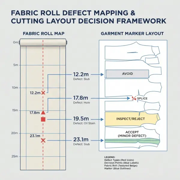
A useful defect map links every validated event to a roll, physical position, image, category, and severity. It may also include inspected length, usable width, roll direction, fabric face, batch, shade group, inspection timestamp, and grading result. The cutting room needs this information in a form it can match to the actual roll.
Once synchronized, the map can support several actions:
- Roll allocation: assign cleaner rolls to styles or colorways with large, prominent panels and use lower-risk material where faults can be managed more easily.
- Splice planning: stop at an appropriate point, remove or bypass a defective section, and restart the lay while preserving ply control.
- Marker review: assess whether a defect falls in a garment component, seam allowance, waste area, or a visually sensitive zone.
- Panel avoidance: shift or recalculate placement where fabric constraints and software capability permit.
- Targeted verification: direct an operator to a specific width and length position rather than slowing the entire roll for continuous manual observation.
- Claim evidence: preserve an image and coordinate record for supplier discussion when incoming material does not meet the agreed specification.
Commercial systems demonstrate how this connection can extend beyond a defect report. Uster describes an optimized cut-control workflow that uses defect maps, customer quality requirements, position synchronization, and operator visualization to support cutting decisions. Its documented inspection-to-cutting functions show what integration can include, but any expected yield gain remains dependent on the factory’s material mix, marker constraints, data accuracy, and operating rules.
The most useful interface is not always a sophisticated optimizer. A reliable roll map, visible mark, and clear stop position may outperform complex automation that does not match the spreading process.
What Can Machine Vision Detect Reliably—and What Is Harder?
Reliability is specific to the validated operating range. High-contrast, discrete, repeatable defects on a stable surface are generally easier than subtle, irregular, subjective, or previously unseen issues. The same defect can move from easy to difficult when fabric color, texture, speed, or illumination changes.
Machine vision may be well suited to configured examples of holes, cuts, obvious stains, missing yarns, dropped stitches, local density changes, recurring lines, certain print-registration faults, and some surface contamination. It can also locate events consistently across long rolls when the web and encoder are stable.
More difficult cases may include:
- low-contrast faults on mélange, printed, hairy, pile, lace, reflective, or highly textured materials;
- acceptable slubs or irregularities that resemble faults but belong to the fabric design;
- gradual shade change across a roll or subtle side-to-side color variation without calibrated color sensing;
- intermittent defects that appear differently from the labelled examples;
- long, thin, or diffuse faults that do not fit conventional bounding boxes well;
- tactile issues, odor, stretch recovery, internal delamination, strength, colorfastness, or chemical non-compliance that surface imaging cannot establish.
A 2025 experiment limited its model to holes, color bleeding, and crease defects on plain, patternless cotton and linen. The study’s deliberately defined material and defect scope is a useful reminder: credible validation says not only what a model detected, but also which fabrics and faults it did not test.
Which Metrics Matter in Production?
Accuracy alone is usually too vague. If normal fabric dominates the dataset, a model can appear accurate while missing the rare defects that matter most. Production teams should evaluate technical and operational measures together.
|
Metric |
Practical question |
|
Recall or sensitivity |
Of the known critical defects, how many did the system find? |
|
Precision |
Of all alerts, how many were genuine defects rather than false alarms? |
|
False-negative rate |
How often did a defect pass undetected? |
|
False-positive rate |
How much unnecessary review or fabric avoidance did the system create? |
|
Per-class performance |
Does the system find every critical class, or only the easiest and most common ones? |
|
Localization error |
Are reported positions accurate enough for spreading and cutting? |
|
Inference latency and throughput |
Can analysis keep pace at the required fabric speed and width? |
|
System availability |
How much production time is covered after maintenance, faults, and changeovers? |
|
Downstream escape rate |
How many machine-inspected defects are later found in cut panels or garments? |
Threshold selection involves a trade-off. Lowering the alert threshold may capture more true defects but increase false positives. Raising it may make review more efficient while allowing subtle faults through. The appropriate balance depends on the cost of a missed defect, the cost of operator review, the end product, and whether the next step includes another inspection opportunity.
A Practical Workflow for Fashion and Garment Businesses
Fashion brands rarely need to design the vision model themselves, but they do need to define the quality problem. A brand sourcing premium plain dresses will prioritize different faults from a sportswear producer using engineered prints or a manufacturer cutting brushed knitwear.
A practical implementation sequence is:
- Start with actual cutting losses. Review recuts, panel rejection, spreading stops, supplier claims, and recurring fabric faults by material family.
- Define the smallest critical defect. State its physical dimensions, contrast, position risk, and garment consequence. This anchors camera resolution and test design.
- Build representative validation sets. Include accepted variation, critical faults, rare serious faults, multiple shades and batches, fabric edges, joins, wrinkles, and real production speeds.
- Test position transfer, not only detection. Confirm whether the team can find the same point after rewinding, relaxation, warehouse movement, and loading onto the spreader.
- Assign human-review rules. Define which confidence bands, defect types, or high-risk orders require verification.
- Pilot one material family and one decision path. For example, scan incoming plain woven fabric and use the map for targeted spreading stops before expanding to prints or knits.
- Measure downstream results. Track defect escapes, false alarms, recuts, fabric utilization, review time, system downtime, and supplier-response quality.
This pilot evidence also prepares management for the broader questions covered in what fashion businesses should verify before adopting inspection technology. A reliable technical demonstration is necessary, but cost, service, integration, data ownership, training, and change management determine whether it becomes a durable operation.
Common Mistakes in Machine-Vision Defect Detection
Comparing model accuracy across unrelated datasets
A 95% result on one benchmark is not automatically better than an 85% result on noisy factory data. Defect classes, fabric types, class balance, image conditions, data splits, and evaluation metrics may all differ. Businesses should request per-class results on representative production samples and record what was excluded from the test.
Training only on obvious defects
Large stains and holes are easy to label and demonstrate, so they can dominate the dataset. The system may then perform poorly on fine needle lines, faint creases, or rare defects that cause greater commercial loss. Dataset planning should follow business risk, not annotation convenience.
Ignoring normal variation
If accepted shade, texture, print, or yarn variation is missing from the normal examples, the system can treat legitimate production diversity as defective. False alerts erode operator trust and can encourage teams to bypass the system. Representative good fabric is as important as defective fabric, particularly for anomaly-detection models.
Losing the coordinate between inspection and spreading
A correct detection is operationally weak if the roll is reversed, trimmed, stretched, remeasured, or relabelled without updating the map. Roll identity and orientation must survive every handoff. Position error should be tested after the actual warehouse and spreading workflow, not only at the inspection machine.
Treating every alert as a cutting prohibition
Not every detected feature affects every garment component. Automatic avoidance without severity and placement rules can reduce yield unnecessarily. The better design separates detection from disposition and applies end-use-specific decisions.
Important Technical Caveats
Machine vision observes optical evidence; it does not independently establish total fabric quality. Laboratory testing, supplier documentation, and human assessment remain necessary for non-visual performance, regulatory requirements, tactile characteristics, and subjective appearance.
Model performance can also change after deployment. New suppliers, yarn lots, finishing recipes, print scales, lighting components, cameras, software versions, or production speeds may shift the image distribution. This is often called model or data drift, although the operational cause may be as simple as dirty optics or an unrecorded lighting adjustment.
The safest approach combines routine reference checks, audit rolls containing known faults, sampled human reinspection, false-negative review, change logs, and retraining or reconfiguration when evidence supports it. A system should not be considered validated forever merely because it passed commissioning.
Frequently Asked Questions
Does machine vision need artificial intelligence to detect fabric defects?
No. Machine vision can use conventional image-processing methods such as edge analysis, thresholding, morphology, texture statistics, pattern comparison, or frequency analysis. Artificial intelligence and deep learning are useful when defects and acceptable variation are difficult to describe with fixed rules, but they require suitable data and validation. Many production systems use a hybrid approach: optical rules stabilize or pre-filter the image, a learned model detects or classifies suspicious regions, and human reviewers handle uncertain cases. The appropriate method depends on fabric regularity, defect diversity, line speed, computing capacity, and the availability of labelled examples.
How small a fabric defect can a camera detect?
There is no universal minimum size. Detectability depends on the defect’s physical dimensions and contrast, the number of pixels covering it, lens and sensor quality, illumination, motion blur, fabric speed, focus, and the algorithm. A fine broken yarn may require more spatial detail than a high-contrast stain of the same overall area. Vendors should express tested capability in millimetres at the fabric surface under stated speeds and lighting conditions. The factory should validate its smallest commercially critical faults across the full fabric width rather than relying only on camera resolution listed in a brochure.
Can a defect map automatically prevent faults from entering garment panels?
It can support prevention, but only when the digital coordinate remains synchronized with the physical roll and the spreading or marker workflow can act on it. The response may involve stopping and splicing, avoiding an area, adjusting placement, or asking an operator to verify the location. Marker constraints, nap direction, pattern matching, roll stretch, rewinding, and position error can limit automatic avoidance. A pilot should measure downstream escape rate—the number of mapped defects still found in cut components—not merely whether the inspection system created a map.
Is anomaly detection better when a factory has few defect images?
It can be a sensible option because it learns acceptable fabric and looks for departures without requiring many labelled examples of every fault. It is not automatically easier. The normal dataset must represent legitimate differences in shade, texture, yarn, print position, batch, edge condition, and process variation. Otherwise, acceptable fabric may generate frequent alerts. Anomaly detection may also identify a suspicious area without naming the problem. Factories should test whether this output is sufficient for their review and cutting decisions and compare false alarms with a supervised or hybrid alternative.
How should a factory validate machine vision before production use?
Validation should use representative rolls at real operating speed and include known critical defects, accepted variation, several batches and shades, edge conditions, fabric joins, and difficult surfaces. Measure recall and precision by defect class, location accuracy after rewinding and spreading, throughput, downtime, and downstream escapes. Tests should be separated from training data and reviewed by people who understand both fabric quality and cutting consequences. The factory should also define acceptance thresholds, audit frequency, change control, and what happens when the system or data connection is unavailable.
Can machine vision evaluate fabric shade and color consistency?
It may detect some visible color patches or print differences when the camera and lighting are suitable, but general surface imaging should not automatically be treated as calibrated color measurement. Shade evaluation depends on illumination spectrum, camera response, white balance, geometry, calibration, fabric direction, and the tolerance being applied. Some installations use dedicated shade-monitoring or color-measurement functions alongside defect inspection. Businesses should verify whether the proposed system measures color quantitatively, detects only local visual anomalies, or simply stores true-color images for human review.
Conclusion
Machine vision helps before cutting when it does three things well: captures the right visual evidence, locates it accurately on the physical roll, and delivers the finding to a team that can still change material use. The algorithm sits in the middle of that chain, not at the beginning or the end.
For textile and apparel operations, the most credible path is therefore specific rather than universal. Define the fabric family, critical defects, minimum observable size, production speed, coordinate accuracy, and cutting response. Validate them together. A model that performs well on disconnected sample images may still fail operationally if the roll map drifts or operators cannot use the alert.
When image acquisition, defect logic, position tracking, and human judgment are aligned, machine vision can move quality control upstream—from discovering defective garment panels to managing risky fabric areas before the first cut is made.





Comments 0
Leave a CommentSend Comment
Anda harus Login terlebih dahulu untuk dapat memberikan komentar.