

CAD Marker Making Explained for Apparel Production
CAD marker making is the digital process of arranging garment pattern pieces within a defined fabric width so they can be cut accurately while using material as efficiently as production constraints allow. It sits between pattern development and fabric cutting, translating graded garment patterns, order quantities, fabric characteristics, and cutting rules into a production-ready layout.
In a modern apparel workflow, marker making is not simply about squeezing shapes together. Pattern pieces may have to respect grain direction, nap, print or stripe matching, allowable rotation, size ratios, spreading methods, and cutting requirements. A layout that appears compact can therefore be technically wrong if it ignores how the fabric or garment must behave.
That is why CAD marker making should be understood as both a geometric optimization task and a production-planning function. Research on apparel marker planning describes it as a two-dimensional irregular packing problem: irregular pattern pieces must be positioned within a fixed-width material surface while minimizing unusable space and respecting manufacturing constraints.
Quick Answer: What Is CAD Marker Making?
CAD marker making is the use of computer-aided design software to arrange garment pattern pieces into a cutting layout called a marker. The marker represents the usable width of the fabric and contains the pieces, sizes, and quantities required for a planned cutting operation.
The software can help operators position pieces manually, automatically nest them, or combine both approaches. Production rules may restrict whether pieces can be rotated, flipped, paired, matched to fabric repeats, or placed in particular orientations. Gerber's marker-making documentation, for example, describes marker making as placing pattern pieces within the material represented by the marker while following limits defined for the order. Optitex similarly allows marker operators to define orders, manipulate pieces, apply orientation constraints, work around unusable fabric areas, and generate material-consumption reports.
For apparel businesses, the practical objective is not merely to create a visually neat layout. A usable CAD marker must connect design data with real production conditions so that the cutting room receives the correct pieces, quantities, orientations, and material assumptions.
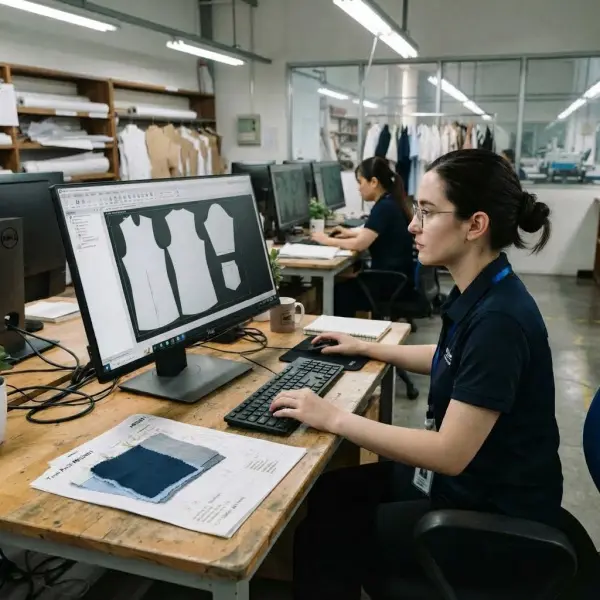
What Exactly Is a Marker in Garment Manufacturing?
A marker is a planned arrangement of the pattern pieces that will be cut from a specified material width. Depending on the production system, it may exist as a digital file, a plotted paper marker placed over a fabric lay, or digital cutting data transferred to compatible cutting equipment.
This distinction matters because a garment pattern and a marker perform different jobs. A pattern defines the shape and construction geometry of an individual garment component. A marker determines how multiple required pattern pieces are arranged together for production. The same graded pattern set can therefore generate many different markers depending on fabric width, order quantities, size assortment, material restrictions, or cutting strategy.
Consider a basic woven shirt available in six sizes. Pattern development may produce fronts, backs, sleeves, collars, cuffs, yokes, pockets, and other components for every graded size. Production does not necessarily place every available size into every marker. The marker may instead contain a particular size ratio based on the order—for example, a greater quantity of medium and large garments than extra-small or extra-large units.
The marker therefore converts pattern information into a cutting-room instruction.
Academic research from Hong Kong Polytechnic University describes marker planning as a critical cutting-room activity in which pattern pieces of different garment sizes or styles are arranged within fixed-width material to increase fabric utilization. Because garment components are irregular shapes rather than convenient rectangles, unused areas inevitably appear between pieces, making the problem considerably more complex than simple area calculation.
CAD marker making is not the same as CAD pattern making
The two functions are closely connected but should not be treated as interchangeable.
Pattern-making software is primarily concerned with creating, modifying, checking, and grading garment pieces. Marker-making software takes those production-ready pieces and determines how they should be positioned for cutting.
In an integrated apparel CAD environment, the workflow can appear seamless because both functions may exist within the same software ecosystem. Operationally, however, they solve different problems. A technically correct pattern can still produce a poor marker, while an apparently efficient marker cannot compensate for incorrect pattern geometry.
Where CAD Marker Making Fits in the Apparel Production Workflow
Marker making usually becomes relevant after the production pattern and grading information are sufficiently stable for cutting preparation. It connects product engineering with material planning and the physical cutting process.
A simplified production flow looks like this:
Approved pattern and grading → production order → cut planning → marker creation → fabric spreading → cutting → bundling → sewing
The exact sequence varies by factory. Some facilities integrate order planning, marker generation, spreading, and automated cutting through connected CAD/CAM systems. Others create digital markers but still plot them onto paper for use with conventional spreading and cutting processes.
The important point is that marker making should use production information rather than hypothetical design assumptions. Fabric width, actual size requirements, spreading method, material direction, and pattern-matching rules can all change the layout.
Modern cut-planning systems may also connect markers directly with order information. Optitex CutPlan, for example, can use style, size, color, fabric, roll, and order information to create marker combinations and spreading plans, while Gerber AccuPlan includes utilization settings related to fabric width, marker length, bundle quantities, and spread types.
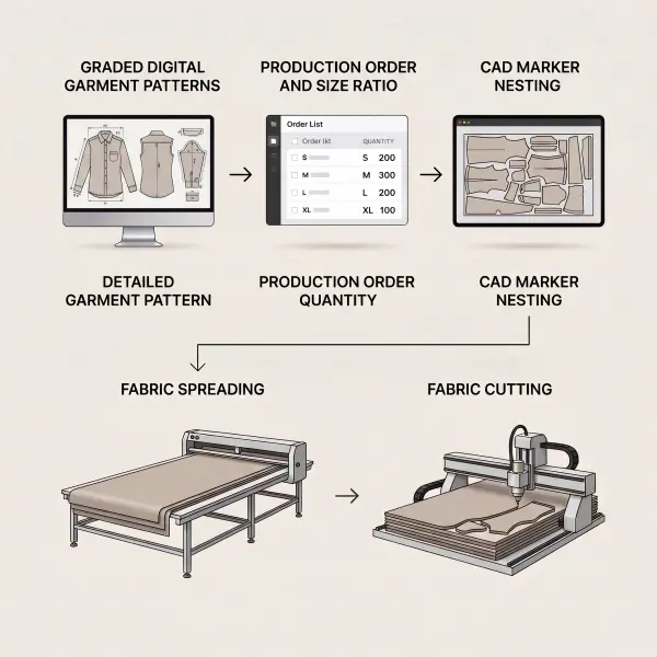

How Does CAD Marker Making Work?
CAD marker making begins by telling the system what must be cut and under what conditions. The software then provides a digital workspace representing the available material width. Pattern pieces can be positioned manually by a marker maker, placed using automated nesting algorithms, or refined through a combination of automated and human decision-making.
The geometric objective sounds straightforward: place every required piece while keeping the marker as compact as possible. In practice, the system must solve that problem without violating garment or material rules.
Gerber's Easy Marking documentation notes that permitted actions such as flipping and rotation depend on limits associated with the marker order. Optitex likewise describes nesting constraints that control piece order and orientation rather than allowing every pattern component to move freely simply because a tighter geometric arrangement is possible.
1. Production pattern pieces are loaded
The marker should begin with the correct production patterns rather than obsolete sample files. The system needs the appropriate style, graded sizes, material grouping, and component quantities.
This sounds basic, but version control becomes important when a style has undergone multiple fit corrections. If the approved sleeve was shortened after the earlier pattern set had already been released to the CAD room, creating a highly efficient marker from the old sleeve provides no production benefit. The resulting cut is simply wrong more efficiently.
2. The required size assortment is defined
Production orders rarely contain equal demand across every garment size. The cutting plan may therefore call for a particular ratio or combination of sizes.
CAD systems can create markers containing multiple sizes and quantities. Gerber's Marker Wizard, for example, allows quantities to be specified for individual sizes, while marker tools from Optitex support bundle quantities and complex size variations.
The size mix can affect how efficiently shapes interlock. A small pattern component may fit naturally into a gap created by a larger size, while a marker containing only one size may create a different nesting problem. This is one reason a marker cannot be evaluated independently of the production order it was designed to serve.
3. Usable fabric width is entered
Marker width should correspond to the usable material available for cutting, not simply a generic nominal width copied from a specification sheet.
Fabric width matters because the CAD system is solving a constrained spatial problem. A different width changes the space available for arranging every piece and can therefore change marker length and the entire nesting solution.
Width variation can also matter operationally. Gerber's planning tools support utilization information for multiple fabric widths, while research into marker planning has shown that fabric width is one of the variables capable of changing marker efficiency.
For factories working with rolls whose usable widths vary meaningfully, treating all inventory as though it has one identical width can make the digital plan less representative of the actual cutting condition.
4. Material and orientation rules are applied
Not every pattern piece can simply be rotated until it fits into an empty space. Grain direction, surface appearance, print orientation, nap, stretch direction, and garment design may constrain placement.
A plain non-directional material may permit more flexibility than a one-way print or a visibly directional brushed fabric. Similarly, turning a pattern piece by 180 degrees may be acceptable for one fabric but produce a visible shade or surface-direction difference in another.
CAD systems therefore use placement rules. Gerber documentation shows examples of piece settings that permit or restrict rotation and flipping, demonstrating that nesting optimization operates inside manufacturing limits rather than outside them.
5. Pieces are nested
Nesting is the process of fitting pattern pieces together within the marker. Automated nesting software can evaluate large numbers of possible placements faster than a person could manually test them one by one.
This does not mean the software merely looks for the smallest empty gaps. Marker planning belongs to a broader class of two-dimensional irregular packing problems, where shapes must be packed compactly without illegal overlap and while satisfying production constraints. Academic work continues to investigate heuristic and metaheuristic approaches to this type of problem, illustrating why marker optimization is computationally non-trivial.
Commercial systems implement their own optimization approaches. Optitex describes automated nesting alongside manual manipulation, while Tukatech's SMARTmark provides automatic marker nesting within its apparel production ecosystem.
6. The marker is checked before release
A numerically strong marker is not automatically a production-ready marker. The operator still needs to verify that the correct sizes, pieces, quantities, orientation rules, material width, and other production requirements have been respected.
This verification is particularly important when parameters have been overridden manually. If a software warning is bypassed merely to gain additional nesting efficiency, the resulting layout may create sewing, appearance, or quality problems later.
What Information Does a CAD Marker Need?
A marker is only as reliable as the information used to generate it. The relevant inputs vary by product and system, but several categories appear repeatedly in apparel production.
|
Marker input |
Why it matters in production |
|
Pattern pieces |
Defines the components that actually need to be cut |
|
Graded sizes |
Determines which size variants are available for the marker |
|
Size quantities or ratio |
Connects the marker with order requirements |
|
Usable fabric width |
Defines the horizontal space available for nesting |
|
Grain or directional rules |
Prevents unacceptable piece orientation |
|
Fabric face/spreading rules |
Influences whether flipping or paired placement is permissible |
|
Nap or one-way requirements |
Prevents visible directional inconsistencies |
|
Stripe, plaid, or print repeat |
May require pieces to align with specific motif positions |
|
Piece matching requirements |
Coordinates visual continuity between garment components |
|
Cut quantity |
Connects the marker to the number of garments required |
|
Spreading/cutting constraints |
Ensures the layout can be executed by the intended production process |
These inputs demonstrate why marker making is not merely a graphic-design exercise. The CAD operator needs enough understanding of garment construction and cutting-room operations to recognize when an apparently attractive placement contradicts the material or production method.
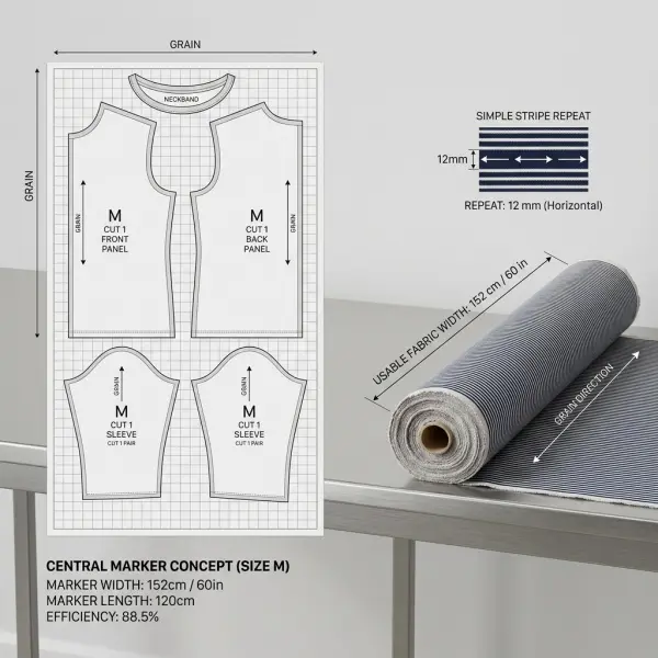
Why Fabric Direction and Pattern Matching Change the Marker
One of the easiest mistakes for non-production teams is to assume that the most tightly packed marker is automatically the best marker. Fabric characteristics can make some geometrically possible placements unacceptable.
Directional fabrics illustrate the problem clearly. Suppose a jacket fabric has a visible nap or surface direction. Turning one front panel upside down to fill an empty space may improve the CAD layout numerically but cause that panel to reflect light differently from the rest of the garment. The garment could appear to contain two different shades even though every component came from the same roll.
Patterned fabrics introduce another layer of constraint. Plaids, stripes, and repeated motifs may need to meet at seams or appear in predetermined positions on specific garment components. Gerber's CutWorks documentation supports fabric repeats, match points, match lines, orientation constraints, and material repeat settings specifically for this type of production requirement.
Those restrictions often create additional unused space because the operator loses some freedom to reposition pieces. Lower numerical efficiency in such a marker does not necessarily mean poor marker making. It may reflect the legitimate cost of maintaining garment appearance.
This is why marker performance must be interpreted against the style and material being cut rather than compared blindly across unrelated products.
What Is Marker Efficiency?
Marker efficiency measures how much of the rectangular marker area is occupied by garment pattern pieces. In its common area-based form:
Marker Efficiency (%) = Total Area of Pattern Pieces ÷ Total Marker Area × 100
The marker area is generally the marker width multiplied by its length. Higher efficiency means a larger share of that defined marker rectangle is occupied by garment components rather than gaps between them.
The concept is central to apparel marker planning because the geometry of the layout affects fabric consumption. Research literature accordingly treats improved fabric utilization as a core objective of marker planning.
However, marker efficiency should not be interpreted as a complete measure of all fabric waste in a factory. Losses caused by roll ends, spreading allowances, defects, splices, recuts, shade problems, or other cutting-room events may occur outside the marker geometry itself. A factory can therefore improve marker efficiency while still having other sources of material loss.
The deeper relationship between efficiency, consumption, and manufacturing waste belongs in how marker efficiency reduces fabric waste in garment manufacturing. For this article, the key point is that CAD provides the environment in which marker utilization can be calculated, compared, and optimized while production rules remain visible.
Why CAD Marker Making Matters for Apparel Production
The value of CAD marker making comes from connecting several decisions that otherwise risk being handled separately: pattern data, order quantities, material characteristics, consumption estimates, and cutting execution.
For a brand or manufacturer, that connection influences more than the CAD department.
Fabric purchasing and costing
Once production-ready markers provide a credible indication of fabric consumption, sourcing and costing teams can work with assumptions closer to the intended production method. This is especially useful when style geometry, size assortment, or fabric width makes consumption difficult to estimate from a single sample size.
The marker should not be treated as the only purchasing calculation, because spreading losses, shrinkage assumptions, defects, testing, and production allowances may still need to be considered. But it creates a much more useful technical basis than estimating material requirements from garment appearance alone.
Cutting-room consistency
Digital marker files can preserve layout rules and reduce dependence on redrawing the same production arrangement repeatedly. They can also integrate with subsequent cutting processes.
Tukatech, for example, describes marker data being transferred to its automated cutting system, while Optitex's marker environment can generate material-related reports and connect with cut planning.
The business advantage comes from repeatability. If an approved marker is clearly identified and controlled, different departments have a common production reference rather than relying on informal interpretation.
Faster evaluation of alternatives
Digital systems make it practical to test alternative marker scenarios before fabric is physically spread. A team might compare two usable fabric widths, change the size combination, or evaluate a different marker grouping.
This does not guarantee that every alternative will be better. It makes comparison less dependent on physically redrawing complete layouts, which can support faster planning when an order contains many styles, sizes, materials, or delivery batches.
Traceable production information
Marker reports can provide information such as marker dimensions, material utilization, style or size content, and other production parameters depending on the software.
That information becomes useful for costing review, production planning, procurement analysis, and post-production investigation. When actual material consumption exceeds the marker-based expectation, the team can ask a more specific question: was the difference caused by the marker itself, or by losses occurring elsewhere in the cutting process?
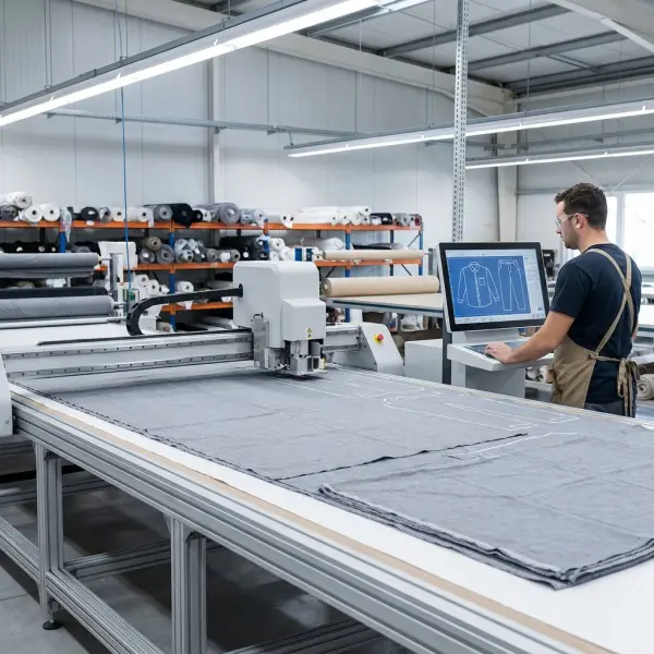
CAD Marker Making Does Not Mean Fully Automatic Decision-Making
Automation can generate highly compact layouts, but CAD marker making still requires correct production rules and informed review. Software cannot infer every commercial or technical requirement if that information has never been entered correctly.
This becomes particularly relevant when teams describe automated nesting as though it can simply "find the best marker." Best according to what objective? A system may optimize material utilization, but the allowable search space is still shaped by fabric width, rotation limits, matching requirements, piece relationships, size combinations, and other parameters.
The output therefore reflects both the optimization capability of the software and the quality of the production data.
Human expertise also remains relevant when trade-offs need interpretation. A marker maker may recognize that a small theoretical efficiency gain creates an awkward cutting sequence, conflicts with actual roll conditions, or depends on an orientation override that should not be used for the material.
Digital tools change how the work is performed; they do not eliminate the need for production judgment. The operational differences between traditional layouts and digital workflows are explored more directly in manual marker vs digital marker.
How Fashion Businesses Can Apply CAD Marker Making Strategically
A fashion brand does not need to operate its own cutting room to benefit from understanding marker making. Brands that outsource manufacturing can use marker information to improve costing conversations, fabric purchasing decisions, supplier evaluation, and investigation of consumption variances.
The first priority should be reliable data rather than advanced automation. Approved production patterns, correct fabric specifications, accurate size quantities, and clear directional requirements must exist before optimization has much value.
Several practical controls are especially useful:
- Confirm the pattern revision used for the marker. The marker should reference the final approved production pattern rather than an earlier sample version.
- Use actual usable fabric width where possible. Nominal supplier width and usable cutting width are not necessarily interchangeable.
- Define directional and matching rules before nesting. Do not optimize first and discover later that pieces were rotated illegally.
- Check the size assortment against the production order. A high-performing marker for the wrong size ratio is operationally useless.
- Record marker length and utilization together with the marker version. This creates a useful baseline for costing and production review.
- Compare planned consumption with actual cutting-room performance. Persistent variance may indicate problems outside the CAD marker itself.
- Evaluate difficult materials separately. Plaids, engineered prints, nap fabrics, or materials with defects may need different marker logic from basic solids.
For smaller brands using contract manufacturers, asking for a marker report can be more informative than simply challenging a factory's consumption figure. It gives both parties something concrete to review: width, marker length, size mix, and layout assumptions.
Important Technical Caveats
CAD marker making should not be treated as a universal optimization problem with one ideal percentage or one correct layout. A marker is valid only within the conditions for which it was built.
Fabric width is one obvious variable, but it is not the only one. Garment geometry, number of pieces, size combinations, grain restrictions, material direction, spreading mode, and print matching can all alter the available nesting options. Research comparing marker configurations has demonstrated that factors such as fabric width and spreading-related parameters can influence marker efficiency, reinforcing the need for context-specific evaluation rather than a universal target.
A second caveat concerns sustainability language. Better nesting can reduce unused material within a marker and can contribute to lower material consumption. It does not automatically make a garment or factory "sustainable." Overall environmental performance also depends on fiber production, dyeing and finishing, energy, transportation, garment durability, production overruns, end-of-life pathways, and many other factors.
Lectra currently identifies marker efficiency, estimation accuracy, material defects, motif alignment, and recuts among cutting-room factors associated with material waste. Its published figures describing typical cutting-room waste should be interpreted as vendor-reported industry guidance rather than a universal benchmark applicable to every factory.
Finally, the theoretical CAD result should be compared with real execution. A marker created for a particular usable width or material condition loses validity if production substitutes a different fabric configuration without reevaluating the layout.
Common CAD Marker Making Mistakes
Optimizing against the wrong fabric width
Entering an assumed width because it appeared on the purchase order can produce a marker that looks efficient on screen but does not represent the roll being spread. If the usable material is narrower, pieces may no longer fit; if it is meaningfully wider, the factory may be missing a better layout opportunity. A stronger process verifies the usable cutting width and manages width variation deliberately.
Allowing illegal rotation to improve the number
The marker may become shorter when a long component is turned, but the resulting garment can be unacceptable when the material has nap, directional print, pile, or another orientation-sensitive surface. The mistake occurs when marker efficiency is treated as the goal rather than one KPI inside a set of production constraints. Correct direction must take priority over cosmetic improvement in the utilization percentage.
Ignoring motif matching until cutting
Stripe and plaid alignment cannot always be repaired during sewing. If selected seams or panels must match, that requirement should influence marker planning and fabric repeat settings before cutting. CAD systems can support repeat and match information, but those capabilities only help when the rules are defined correctly.
Using the wrong size ratio
A technically perfect layout can still create the wrong production quantities. This often happens when marker creation is separated from order planning and the CAD operator works from an outdated ratio. Marker content should therefore be reconciled with the actual cut order before release.
Treating marker efficiency as total fabric utilization
Marker efficiency describes the geometry inside the marker. Actual fabric usage can also be affected by roll ends, spreading losses, defects, recuts, and other production events. When actual consumption is higher than expected, simply blaming the marker may send improvement efforts toward the wrong problem.
Assuming automatic nesting removes the need for verification
Automated nesting can test layouts efficiently, but it cannot protect production from incorrect master data. Wrong pattern revisions, inappropriate orientation permissions, inaccurate fabric width, or incorrect quantities can all be optimized successfully from a mathematical perspective. The final marker still needs a production check.
What Should Brands Verify Before Approving a Production Marker?
For a brand reviewing markers supplied by an external manufacturer, the most useful questions are not simply "What is the marker efficiency?" or "Can you improve it?"
Start by confirming what the marker actually represents. Which pattern revision was used? What is the usable fabric width? Which sizes and quantities are included? Are there one-way, nap, grain, stripe, plaid, or placement restrictions? Is the marker intended for single-ply or multi-ply cutting? How will the layout translate into the factory's actual spreading and cutting process?
Only after those conditions are understood does the utilization figure become meaningful.
This approach also makes supplier conversations more constructive. A factory may have a legitimate reason for a less compact marker when the garment contains large asymmetric pieces or strict motif matching. Conversely, a surprisingly high utilization figure deserves investigation if it depends on placements that violate fabric direction.

FAQ About CAD Marker Making
Is CAD marker making only used by large garment factories?
No. CAD marker making can be useful anywhere repeatable digital pattern and cutting preparation justify the software, training, and workflow. Large factories may gain more from automation because they process high volumes and many markers, but smaller manufacturers, sample rooms, fashion studios, and service providers can also use digital markers. The business case depends on production volume, style complexity, outsourcing arrangements, software cost, existing CAD infrastructure, and how frequently markers need to be revised.
Can CAD marker software automatically create the most efficient layout?
CAD systems can automatically generate optimized layouts, but "most efficient" is conditional on the rules supplied to the system. Orientation, size mix, fabric width, print matching, allowable rotation, and other constraints change the solution space. Some systems also let operators combine automatic nesting with manual placement. The correct objective is therefore not maximum geometric compactness at any cost, but strong material utilization within legitimate production requirements.
What is the difference between nesting and marker making?
Nesting refers specifically to arranging shapes compactly within the available material area. Marker making is the broader production activity that establishes the marker and its requirements, including the pieces, sizes, quantities, width, placement rules, and final layout. Automated nesting can therefore be one function within a CAD marker-making workflow rather than a synonym for the entire process.
Does a higher marker efficiency always mean a better marker?
No. Higher marker efficiency is valuable only when the marker remains technically correct and executable. A lower-efficiency marker may be appropriate when fabric has a directional nap, large repeat, stripe or plaid matching requirement, asymmetric pattern pieces, or restrictive grain rules. Comparing percentages without comparing the underlying production conditions can therefore be misleading.
Can a CAD marker be sent directly to an automatic cutting machine?
In compatible CAD/CAM workflows, digital marker or cutting data can be transferred to automated cutting equipment. The exact process depends on software, machine, file compatibility, and the factory's production configuration. Tukatech, for example, describes marker cut data being transferred to its TUKAcut system through the CAD network or other supported methods.
Does CAD marker making eliminate fabric waste?
No. CAD marker making can help reduce unused space within the marker and support more accurate material planning, but some geometric waste remains because irregular garment pieces do not normally tile a rectangular fabric surface perfectly. Additional losses can also occur during spreading, cutting, defect management, roll changes, and recutting. Claims of "zero waste" therefore require a much broader design and production strategy than simply installing marker software.
Should a fashion brand ask its manufacturer for marker data?
For styles where fabric consumption materially affects cost, marker information can be useful. The brand does not necessarily need the factory's complete CAD file, but marker width, length, size ratio, utilization, and pattern revision can help explain costing assumptions and consumption changes. This becomes particularly valuable when fabric is expensive, ordered specifically for the brand, or showing unexpected usage variance during production.
Conclusion
CAD marker making is the point where garment pattern geometry meets the realities of production. It converts graded pattern pieces and order requirements into a cutting layout constrained by material width, garment quantities, fabric direction, motif matching, spreading rules, and cutting capability.
Its importance is easy to underestimate because the output often looks like little more than irregular shapes packed into a rectangle. Behind that rectangle, however, are decisions that influence fabric requirements, cutting accuracy, order quantities, costing, and production repeatability.
Digital nesting can make those decisions faster and more measurable, but software does not replace reliable production data or technical judgment. A compact marker is useful only when it contains the correct pieces, respects the material, reflects the actual order, and can be executed correctly on the cutting floor.
For apparel businesses, that is the most useful way to evaluate CAD marker making: not as software that automatically removes waste, but as a production-control system that makes the relationship between patterns, fabric, orders, and cutting considerably more visible and manageable.





Comments 0
Leave a CommentSend Comment
Anda harus Login terlebih dahulu untuk dapat memberikan komentar.